 |
Back to Cross index | REQUEST PRODUCT INFORMATION! |
|
2089-24 Downconverter, 2.0-2.4 GHz |
||
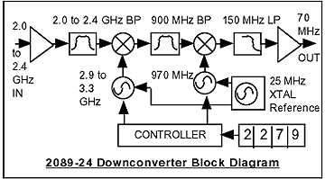
| The Series 2089-24 Downconverter converts 2.0 - 2.4 GHz to a 70 MHz IF with no spectrum inversion, high linearity, good phase noise, flat frequency response, and 1 MHz tuning steps. The 2.0 - 2.4 GHz input is mixed with synthesized local oscillator (LO) signals, first to 900 MHz and finally to 70 MHz IF. Front panel LEDs indicate DC power is applied (green) and if a PLL alarm occurs (red). The gain is set at 10 dB . Connectors are type N female for the RF input and BNC female for the IF output. The 2089-24 is housed in an 1 3/4” X 19 “ X 14 “ deep rack mount chassis. | ||

2089-24 Downconverter Front

Equipment Specifications*
| Input Characteristics | |
|
Impedance/RL Frequency Noise Figure Level Range Input 1 dB compression |
50 ohms/10dB 2.0-2.4 GHz 15 dB max -20 to -30 dBm -10 dBm |
| Output Characteristics | |
|
Impedance/RL Frequency Level, max linear Output 1 dB compression |
75 ohms/15dB 70 ± 10 MHz -10 dBm 0 dBm |
| Channel Characteristics | |
|
Gain Image Rejection Spurious Response Frequency Response |
10 ± 1.0dB > 45 dB, min; > 50 dB typ < -50 dBC in band ±1.5dB, entire band; ±0.5dB, any 10 MHz incr. |
| Synthesizer Characteristics | |
|
Frequency Accuracy Phase Noise (dBC/Hz) |
±25 kHz max over
temp <= -75, 10 kHz; <= -90, 100 kHz; <=-100, 1 MHz |
| Controls, Indicators | |
|
Frequency Select DC Power PLL Alarm |
BCD switches
select input left freq in 1MHz steps Green LED Red LED |
| Other | |
|
RF
Connectors IF Connectors Size Power |
type N, female BNC, female 19 inch standard chassis, 1.75"H X 14.0"D 90-260 VAC, 47-63 Hz, 30W max |
*+10 to +40 degrees C; Specifications subject to change without notice