
|
Back to Cross index | REQUEST PRODUCT INFORMATION! | ||||||||||||||||||||||||||||||||||||||||||||||||||||||||||||||||||||||||||||||||||||||||||||||||||||||||||||||||||
|
2087-XXX Downconverter, L-Band, Fixed
Frequency
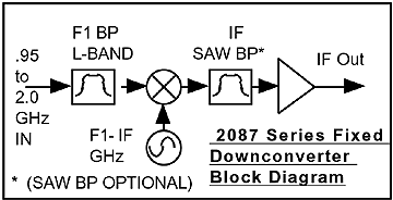
The 2087-XXX Downconverter converts an X.XX GHz L-Band signal (0.95-1.75 GHz) to IF with no spectrum inversion, low group delay, and flat frequency response. The L-Band input is mixed with a fixed frequency local oscillator (LO) signal to 70 or 140 MHz (specified by the customer). The L-Band frequency is fixed and specified by the customer. A green front panel LED lights when DC power is applied and a red LED lights if the phase lock loop for the LO is in alarm. Connectors are BNC female for the IF output and Type F female for the RF input. Power is provided by a 120 ± 10% VAC, 60Hz, wall mount power supply. The 2087 Downconverter is housed in a 4.7” wide X 1.75” high X 12.5” deep aluminum chassis. The 2087 has the option to be mounted on an 1 3/4” X 19 “ rack mount panel (option -R). The 2087 can also be powered by the 2000-01 switching power supply using option -C which includes no power supply. Option -A includes automatic gain control (AGC) for a -25 to -65 dBm input range, an AGC/MGC switch, MGC adjust, and AGC gain monitor. Option -S provides a SAW IF filter.  Front (with AGC and SAW options) and Rear Panel
|
||||||||||||||||||||||||||||||||||||||||||||||||||||||||||||||||||||||||||||||||||||||||||||||||||||||||||||||||||||
