
|
|
Back to Cross index | REQUEST PRODUCT INFORMATION! | |||||||||||||||||||||||||||||||||||||||||||||||||||||||||||||||||||||||||||||||||||||||||||||||||||||||||
|
2015-52 Upconverter, 5.2 - 5.3 GHz, 140 MHz IF
The 2015-52 Upconverter converts 140 ± 36 MHz to 5200 to 5300 MHz in 1 MHz steps with low group delay and flat frequency response. Synthesized local oscillators (LO) provide frequency selection as selected by front panel multi-function push button switches. Front panel LEDs provide indication of DC power (green), carrier Mute (yellow), and PLL alarm (red). Frequency settings appear on the LCD display. Connectors are Type N female for RF and BNC female for the IF signal. Powered by a 90-260 VAC power supply, and mounted in a 1 3/4 X 19 X 16 rack mount chassis. 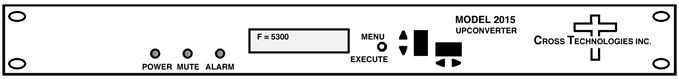 Front Panel 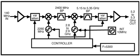 Block Diagram
|
|||||||||||||||||||||||||||||||||||||||||||||||||||||||||||||||||||||||||||||||||||||||||||||||||||||||||||