
|
|
Back to Cross index | REQUEST PRODUCT INFORMATION! |
|
2005-04, -05 Agile Satellite Test Upconverter |
||
| The 2005 Test Upconverter converts a 70 or 140 MHz IF signal to 950 to 2050 MHz (-02) or 950 to 1450 (-03) in 1 MHz steps using a synthesized 1020 - 2120 MHz (-02) or 800 - 1600 MHz (-03) local oscillator (LO) signal. Four BCD switches control the synthesized LO and the output frequency. A green LED lights when DC power is applied. The mixer output is applied to the output amplifier providing a -25 dB or -5 dB gain. Power is provided by the LNB voltage from the receiver under test and connectors are BNC female for the 70 MHz input and F, female for the RF output. An external power supply (option -P) and rack mounting (option -R) is available. | ||
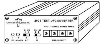
2005 Agile Test Upconverter Front
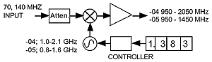
2005 Agile Test Upconverter Block
Diagram
Equipment Specifications*
| Input Characteristics | |
|
Impedance/RL Frequency Level, max Input 1dB |
75 ohms/12dB 70 or 140 MHz left -10 to -20 dBm 0 dBm |
| Output Characteristics | |
|
Impedance/RL Frequency |
75 ohms/8dB 0.95-2.05 GHz (-04), 0.95-1.45 GHz (-05) |
| Channel Characteristics | |
|
Gain Spurious Response Frequency Response |
-25dB ±3dB (low
gain); -5dB ±3dB (high gain) NA; output not filtered ±4dB, 0.95-2.05 GHz; ±0.5dB, any 10 MHz incr. |
| Synthesizer Characteristics | |
|
Frequency Accuracy Frequency Step Phase Noise (dBC/Hz) |
±25kHz max 1.0 MHz min <= -80, 10kHz; <= -90, 100kHz; <= -100, 1MHz |
| Controls/Indicators | |
|
Frequency Selection PLL Alarm DC Power |
Direct readout
BCD switches Red LED Green LED |
| Other | |
|
RF
Connectors IF Connectors Size, Bench Top Size, Rack Mount (-R) Power AC Power (-P) |
type F, female BNC, female 4.7"W X 1.75"H X 6.5"D 19 inch standard chassis, 1.75"H X 7"D (optional) +14 to +20 VDC, 180mA on RF In 120 ± 10% VAC, 60Hz, 10W max, wall mount power supply (optional) |
*+10 to +40 degrees C; Specifications subject to change without notice