
|
|
Back to Cross index | REQUEST PRODUCT INFORMATION! |
|
2004-10 Agile Satellite Test 2.0-2.4 GHz Upconverter |
||
| The Model 2004 -10 converts a 70 or 140 MHz IF signal to 2000 to 2400 MHz in 1MHz steps with a high side or low side 1.8 to 2.54 GHz LO. The IF input is mixed with a synthesized 1.8 to 2.54 GHz local oscillator signal. Up and down tune push buttons control the output frequency displayed on the LED indicators . Pushing these switches simultaneously allows selection of high side LO (C) or low side LO (Ku) and 70 or 140 MHz input. PLL alarm lights red LED when the PLL is unlocked and goes to an open drain FET output. Yellow LED indicates remote operation. An output switched attenuator provides IF to RF gains of -25dB, -45dB, or -65dB. Powered by a wall power supply; connectors are BNC female. Rack mount option -R. | ||
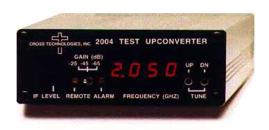
2004-10 Agile Test Upconverter Front
2004-10 Agile Test
Upconverter Block Diagram
Equipment
Specifications*
| Input Characteristics | |
|
Impedance/RL Frequency Level, max Input 1dB/3rd Order |
75 ohms
unbalanced/15dB 70 or 140 MHz left -10 to -20 dBm +5/+15 dBm |
| Output Characteristics | |
|
Impedance/RL Frequency Level |
75 ohms
unbalanced/10dB 2.0 - 2.4 GHz, 70 or 140 MHz high or low side LO selectable -35dBm, -55dBm, or -75dBm with -10dBm in |
| Channel Characteristics | |
|
Gain, max Spurious Response Frequency Response |
selectable -25, -45, -65 dB ±3dB NA; output not filtered ±0.7dB, over 10MHz |
| Synthesizer Characteristics | |
|
Frequency Accuracy Frequency Step Phase Noise |
±50kHz
max 1.0 MHz min Suitable for 128 kB/s QPSK with 1/2 rate FEC |
| Controls/Indicators | |
|
Frequency Selection Output Level PLL Alarm Remote |
PB
switches w/ direct frequency readout Potentiometer and Toggle switch adjustments Red LED (w/ FET open drain) Yellow LED |
| Other | |
|
RF, IF Connectors Size, Bench Top Size, Rack Mount (-R) Power, for -32 |
BNC,
female 4.7"W X 1.75"H X 12.5"D 19 inch standard chassis, 1.75"H X 13"D (optional) 120 ± 10% VAC, 60Hz, 20W max, wall mount power supply |
*+10 to +40 degrees C; Specifications subject to change without notice