 |
Back to Cross index | REQUEST PRODUCT INFORMATION! |
|
1584-25 RF Splitter |
||
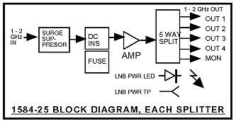
| Each unit contains two, five way, 0.95 - 2 GHz, 0 dB gain splitters in a 1 Rack Unit chassis. Each splitter has a monitor connector on the front panel and four outputs on the back panel. Two individual 115 VAC input power supplies provide a diode OR’d + 22 VDC voltage to power the LNBs through DC power inserters. Each LNB power line is separately fused. A surge suppressor on each LNB input protects against high voltage transients. On the front panel, green LEDs indicate presence of +22 VDC at each LNB power supply output and DC voltage test points allow monitoring the LNB voltage with a voltmeter. | ||

1584-25 RF Splitter Front Panel

1584-25 RF Splitter Rear Panel

Equipment Specifications*
| Input Characteristics | |
|
Impedance/RL Level |
75 ohms/10dB, min,
0.95-2.05 GHz; 14dB, typ, 0.95-1.75 GHz -20 dBm total maximum |
| Output Characteristics | |
| Impedance/RL | 75 ohms/10dB, min, 0.95-2.05 GHz; 14dB, typ, 0.95-1.75 GHz |
| In-Band Characteristics | |
|
Gain Freq Response; .95-1.75GHz Freq Response; 1.75-2.05 GHz Port to Port Isolation Coupler to Coupler Isolation |
0 dB ± 1.0 dB ±1.0dB; ±0.5dB, any 20 MHz incr. +1, -3 dB; ±0.7dB, any 20 MHz incr. >18dB min, 20dB typ. >35dB min, 40dB typ. |
| Indicators | |
|
Power |
Green LED indicates DC voltage prior to diode OR and to LNBs |
| Other | |
|
LNB DC
Voltage Output LNB current Surge Suppressor Mechanical Power |
22 ± 2 VDC 300 ma, max, each SiDACTOR 19" standard chassis; 1.75"H X 12"D 90-260 VAC, 50-60Hz, 30W; Redundant switching power supplies |
*+10 to +40 degrees C; Specifications subject to change without notice